Air admittance valves (also referred to as Durgo valves) are used to provided internal venting for soil and ventilating stacks - this can either be within rooms or the roof space. One great advantage of air admittance valves is that they remove the need for holes through the roof or external walls. They use also reduce the amount of pipework needed to fit an external, open soil or ventilating stack.
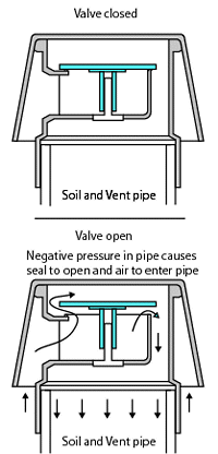
The air admittance valve incorporates a sealing diaphragm which under its own weight or slight spring pressure is normally held closed, thus sealing the foul air within the pipework - see diagram right.
When an appliance discharges into the drain, a slight negative air pressure is produced in the drain pipework which lifts the sealing diaphragm and allows air to be drawn in - see right lower. This intake of air equalises the air pressure and the sealing diaphragm falls back sealing the valve. The inrush of air through the open valve prevents the foul air in the pipe from escaping into the room/roof space and prevents the water seals in traps along the pipework from being broken.
An air admittance valve must be installed so that it is positioned above the highest flood level of the appliances fitted to the pipe - that is to say, where a washbasin is connected to the pipework, the air admittance valve must be higher than the overflow of that basin. This is to ensure the correct operation of the air admittance valve, otherwise there is a risk that the water seal in the basin's trap may be broken.
The use of air admittance valves are governed by building regulations (Part H) and they cannot be used in all situation, these regulations should be checked before specifying the use of an air admittance valve - generally speaking, within a normal, two storey house with an existing vent pipe, there will be no problem; fitting within a taller building or a block of flats may be problematic.
Air admittance valves are easy to fit, some incorporate seal rings which seal against the inside of the pipework, other valves just slip onto the top of the vertical pipe. The two main constraints when fitting Air Admittance Valves are:
They can only be fitted to vertical pipework - turning the valve on its side will mean that the seal won't work.
They should only be fitted within a building to avoid the risk of them freezing during winter frosts. Most air admittance vales are supplied with a formed polystyrene moulding, which should be fitted to the valve top after installation in an unheated roof space to provide added protection from frost.
Problems can arise where air admittance valves are fitted to vent pipes which are not separately vented and which include water traps - this can lead to back pressure in the pipework when an appliance is discharged which will effect the appliance discharge - this will be especially noticeable when a toilet is flushed.
Air admittance valves do not need any maintenance but can cause problems if they become faulty as they may allow sewer gas into the building.
A few years ago we had a durgo valve fitted in our family bathroom (built in next to the sink unit and boxed in) to free up the space taken by the original vent pipe.
Since then we have had the intermittent problem of a foul smell in the bathroom which is gradually occurring more and more.
Since my children left home this bathroom is not in daily use.When the smell occurs (at least once a week) I have checked and it is not coming from the bath, bidet, sink or WC as far as I can tell.If I flush the appliances it does not seem to make any difference. Does this sound like a faulty durgo valve or is there another likely cause?
Also the valve is below the basin waste height, being under the counter top.Is this OK?
Posted: Wed Nov 07, 2007 7:12 pmPost subject: durgo smell problem
By the nature of durgos ( automatic air admittance valves ), they should not be fitted as an alternative to natural ventilation, as they are not ventilation at all. Unless faulty they don't smell. If the spring goes they smell something rotten, and allow methane into the room. Not nice at all.
As for the height they should be fitted, the manufacturers stipulate they should be fitted above flood level.
Some plumbers like to fit them one metre above FFL ( finished floor level ), but if the water is getting that high, its been coming out over the toilet for some while, so in theory they only need to be some short distance above the rim of the WC. As just about every WC measures 16" ( except disabled suites , 18" ), 20" should be enough[/i]
Your problem with bathroom smell and the installation you describe is almost exactly the same as ours.
The main difference appears to be that we notice foul smell mainly first thing in the morning, not during the daytime.
I would be very interested to know what you have actually done to try to eliminate the smells and to what extent you have been successful.
My thoughts at the moment tend towards having the vent pipe directed horizontally through the wall (below worktop height so that it is still not visible from inside the bathroom) and then up the wall to terminate above eaves level.
I am still trying to get the original plumber/installer in to look at the problem and get his observations.
Before beginning construction, we arrange for an electrician to set the temporary meter base for the construction site.
First, we need to consider this: where is suitable location for the temporary meter base? and the voltage? number of phases? and type of metering?
The consumer applying for temporary service will be required to supply a suitable pole and meter loop set at the desired location, with the top of the pole at least 16 feet above ground level and no less than three feet below ground level. pics from: www.slio.gov.tw/Service_FileDL.aspx?Departid=5
As a result, builders often have to find a temporary power solution for the jobsite. An important part of choosing the right temporary power solution is ensuring that it's a safe, reliable power source. Temporary power systems can be dangerous if they aren't handled correctly. Because many workers are unaware of the potential electrical hazards of these systems, they become more vulnerable to the danger of electrocution. With a little knowledge, builders can choose the right temporary power source for their jobsite and provide a safer working environment for their team. (via:http://www.hgtvpro.com/hpro/... )
Common mistakes made around electrical power supplies
There are many mistakes you can make that can lead to serious or even fatal injuries. It's important to recognize these and correct them before injury occurs. The following are a few items to look out for on a jobsite: (via:http://www.hgtvpro.com/hpro/... )
Don't allow trades to overload normal-duty extension cords that are connected to temporary power.
Make sure workers never get closer than 10 feet to power lines. Power lines carry a very high voltage. Use non-conductive wood or fiberglass ladders when working near power lines; don't allow workers to use metal ladders.
Keep all extension cords that are plugged into temporary power away from standing or flowing water.
Inspect extension cords to make sure they're not damaged or frayed and that they have a secure grounding lead. Only someone qualified to repair cords should try to fix one. Black electrical tape isn't a way to fix damaged insulation on extension cords.
Confirm that all temporary power is properly grounded and protected from the weather.
Make sure that all buried cables are marked properly to alert trades of their location.
Be sure all work receptacles are GFCI-protected. A GFCI protects workers from shock if the grounding system fails. If the GFCI detects a fault that exceeds 5 milliamps, it shuts off the electricity in 1/40th of a second.
Coming into contact with an electrical voltage can cause current to flow through your body, resulting in electrical shock and burns. Low voltage doesn't mean low hazard, because if the voltage is low, the body could be part of the electrical circuit longer. Electricity has long been recognized as a serious workplace hazard, exposing workers to electrical shock, electrocution, burns, fires, and explosions. (via:http://www.hgtvpro.com/hpro/... )
Options for choosing a temporary power system
There are three options available to provide safe electricity to the jobsite during construction. The first option is a power pedestal that is incorporated into the home's final electrical system. The pedestal and an electrical meter are mounted on a permanent post and a power cable is run underground to the main electrical panel. The meter is usually installed immediately after the foundation is completed. The electrical panel can be temporarily installed on the pedestal, protected from the weather, and later moved into the home, if necessary. Builders generally won't have to pay a fee for this temporary hookup, but there are strict rules about where the pedestal can be placed and what equipment must be used for installation. (via:http://www.hgtvpro.com/hpro/... )
The second option is a temporary service, which can be set up and used to power more than one site. These services may be more expensive and time consuming than using a power pedestal or a gas-powered generator. These can be set up in two different ways. The first way brings the power underground to a temporary location and the other way provides temporary power by setting up a power pole. The height, depth, and bracing of the power pole are all determined by local codes, and the minimum height if the pole comes in over a road is 18 feet. Both methods of providing temporary power through a service require an electrical panel, a meter socket, and a ground fault circuit interrupter (GFCI), all of which need to be protected from the weather. (via:http://www.hgtvpro.com/hpro/... )
The third option is a gas-powered generator. This is a stand-alone, portable unit that the builder can take and place anywhere on the jobsite. Though relatively inexpensive, these units can be noisy and require time to fuel and maintain. Also, gas-powered generators may not supply sufficient amperage for an electric compressor, so builders may also need to purchase a stand-alone compressor unit. (via:http://www.hgtvpro.com/hpro/... )
The builder should evaluate each option and choose the one that best suits their jobsite and complies with local and national safety code.
By understanding the common safety issues involved with temporary power systems, builders can minimize the risk of onsite injuries. The best practice for ensuring that a temporary power solution is safe is to plan carefully and make sure the power system is properly installed and used. (via:http://www.hgtvpro.com/hpro/... )
I find the website, that will help me to understand about "Temporary Drainage", cause temporary drains and waterways are so important for building site....then, I had to use "BA100", so nice.
-PDF/Adobe Acrobat -
Appendix B Calculation for Hinterland Drainage in Northern Section. Appendix C Calculation for Temporary Drainage for Collection of Site Runoff in Northern ... www.ccjv.com.hk/ep_temporary_drainage/revised_temp_drain.pdf
CCECC & CRWJ Joint Venture
Detailed Design of Temporary
Drainage Works
Contract No.HY/2003/19
Improvement to Tung Chung Road
between Lung Tseng Tau and Cheung Sha
Contract No. HY/2003/19 Improvement to Tung Chung Road Between Lung Tseng Tau and Cheung Sha
Detailed Design of Temporary Drainage Works
CCJV Page 1 of 10
CONTEXT
1.0 Introduction...................................................................................................................2
2.0 Backgound .....................................................................................................................3
3.0 The Site and Road Improvement Proposals ...............................................................6
4.0 Engineer’s Requirements For the Drainage System..................................................6
5.0 Drainage Design Parameters........................................................................................7
6.0 The Proposed Drainage Scheme ..................................................................................7
7.0 Detailed Construction Considerations ........................................................................8
7.1 Hinterland drainage .............................................................................................9
7.2 Pipe......................................................................................................................9
7.3 Temporary surface drainage................................................................................9
7.4 Protection of existing streams .............................................................................9
7.5 Haul road sections .............................................................................................10
APPENDIX
Appendix A EPD’s Comments dated 21 Dec 2004 and Response to Comment Table
Appendix B Calculation for Hinterland Drainage in Northern Section
Appendix C Calculation for Temporary Drainage for Collection of Site Runoff in Northern
Section
Appendix D Calculation for Temporary Drainage Pipe (Including support) Design in
Northern Section
Appendix E Calculation for Hinterland Drainage in Southern Section
Appendix F Calculation for Temporary Drainage for Collection of Site Runoff in Southern
Section
Appendix G Flooding Plan
Appendix H Calculations for Filter Tank and Oil Interceptor
Appendix I Outfall Detail
Contract No. HY/2003/19 Improvement to Tung Chung Road Between Lung Tseng Tau and Cheung Sha
Detailed Design of Temporary Drainage Works
CCJV Page 2 of 10
1.0 INTRODUCTION
CCECC and CRWJ Joint Venture (CCJV) has been awarded the Highways Department
Contract No. HY/2003/19 for the Improvement to Tung Chung Road between Lung
Tseng Tau and Cheung Sha. CCJV has employed ESA Consulting Engineers Ltd. to the
temporary drainage designer to carry out the necessary design and calculations.
According to Condition 2.4 of the EP-170/2003 “A drainage system shall be constructed
and operated before the commencement of widening and realigning works for the
section of Tung Chung Road between Lung Tseng Tau and Pak Kung Au. The drainage
system shall be effectively designed, constructed and operated to avoid discharging
construction site runoff into the streams and to transfer all runoff during construction
and operation to the Wong Lung Hang nullah in Tung Chung for discharge. No runoff
during construction and operation shall be discharged into Tung Chung Stream as
shown in Figure 1 of this Permit. The Permit Holder shall, no later than one month
before the commencement of construction of the section of Tung Chung Road between
Lung Tseng Tau and Pak Kung Au, deposit with the Director three hard copies and one
electronic copy of the drainage proposal(s) showing the detailed design, layout and
capacity of the drainage system, the discharge location(s) and the treatment method(s)
before discharge. Before submission to the Director, the proposal(s) shall be certified
by the ET Leader and verified by the IEC as conforming to the information and
recommendations contained in the approved EIA Report (Register No. AEIAR-061/2002)
to mitigate environmental impacts of water quality and ecology.”
According to Condition 2.5 of the EP-170/2003 “The section of Tung Chung Road
between Pak Kung Au and Cheung Sha shall be divided into small catchments for
carrying out the works of the Project. A temporary drainage system shall be constructed
and operated for each catchment to collect construction site run-off for treatment before
discharge. The temporary drainage system shall be constructed in advance of haul road
formation. Sedimentation or filter tanks and oil interceptors shall be effectively designed,
constructed and operated to treat the construction site run-off before discharge into
streams or via the Pui O Wan outfall. To avoid discharging runoff during operation into
the streams within the country parks, an operational drainage system shall be
constructed and operated to convey the runoff during operation to the sea. The Permit
Holder shall, no later than one month before the commencement of construction of the
section of Tung Chung Road between Pak Kung Au and Cheung Sha, deposit with the
Director three hard copies and one electronic copy of drainage proposal(s) showing the
detailed design of the catchments, drainage systems, sedimentation or filter tanks, oil
interceptors and discharge locations. Before submission to the Director, the proposal(s)
Contract No. HY/2003/19 Improvement to Tung Chung Road Between Lung Tseng Tau and Cheung Sha
Detailed Design of Temporary Drainage Works
CCJV Page 3 of 10
shall be certified by the ET Leader and verified by the IEC as conforming to the
information and recommendations contained in the approved EIA Report (Register No.
AEIAR-061/2002) to mitigate environmental impacts of water quality and ecology.”
2.0 BACKGOUND
In accordance with the E.P. condition 2.4 and 2.5, Temporary Drainage Proposal
comprising the following document and drawings were deposited to Environmental
Protection Department on 28 September 2004 by The Engineer:
- Detailed Design of Temporary Drainage Works (Issue 4); and
- ET’s Certification Document;
- IEC’s Verification Document; and
- Drawing Nos:
ESA/041270/General/GB001 (RevB)
ESA/041270/North/DN001 to DN008 (Rev B)
ESA/041270/South/DN001 & DN002 (Rev B)
ESA/041270/South/DN003 (Rev C)
ESA/041270/South/DN004 to DN007 (Rev B)
ESA/041270/DETAILS/DT001 (Rev B)
ESA/041270/DETAILS/DT002 (Rev C)
ESA/041270/DETAILS/DT003 (Rev B)
EPD’s comments (Appendix A) dated 21 Dec 2004 regarding the submitted Temporary
Drainage Proposal was received on 3 Jan 2005. This revised proposal has incorporated
the EPD’s comments as well as some technical changes on the previously submitted
temporary drainage proposal as stipulated as below:
1. According to EIA section 6.3.3.6, “For the northern section of the new road, it is
proposed that a drainage system be constructed ahead of the main roadworks such
that it may be used to discharge the construction site runoff, thus avoid discharging
construction site runoff into the streams. The same system will remain in place and
form the permanent operational drainage system which will avoid discharging
carriageway runoff into the streams together.” According to EIA section 6.3.3.13(i),
“Ch1000 to 32000 - it is necessary to construct the connection to the nullah to allow
for the discharge of run-off to be undertaken in the first instance……..This section
of the drainage system is off-line, running along the west side of the road.”
Therefore, Permanent 1200 dia. pipe along the Maintenance Access Track (approx.
Contract No. HY/2003/19 Improvement to Tung Chung Road Between Lung Tseng Tau and Cheung Sha
Detailed Design of Temporary Drainage Works
CCJV Page 4 of 10
Ch1100 to 1700) would be installed according to the recommendation in the EIA
instead of the temporary 225/ 300 u-channel and Type 1/ 2 pipe from Lung Tseng
Tau to Shek Mun Kap Road for the temporary drainage design purpose. As 1200
dia. pipe is permanent drainage works, Sedimentation tank NFT1 would then be
installed at Shek Mun Kap for filtering the construction runoff before the water
discharge into the 1200 dia. pipe. During the construction of 1200 dia. pipe,
temporary earth bund/ channel would be formed peripherally at the edge of site
boundary and sump pits/ sand trip would be erected at the local low points to collect
the construction runoff so as to prevent the construction runoff directly discharged
outside the Project site. This can prevent the untreated construction runoff going
into the Tung Chung Stream during construction stage and reduce possible
construction wastes and contamination to the surroundings during the removal of
intended temporary drainage works in the previous submission. Moreover, this can
minimize the conflict in construction between the permanent works (1200 dia. pipe
and maintenance access) and intended temporary drainage works in the previous
submission because of the limited working space. Making use of the 1200 dia. pipe
as a temporary drainage measure is a more practical solution to suit the actual site
conditions.
2. Sedimentation tank NFT2 would be installed at approx. Ch1010, the downstream of
the temporary drainage system, to filter the water collected within the site from
Ch1000 to Ch1630 before discharging to the existing manhole S19* through the
crossroad pipe.
3. Minor amendment in the alignment of 600 U-channel from Ch1120 to Ch 1145 to
suit actual site condition.
4. Minor amendment in the alignment of 300 U-channel at Ch1250 to cater for the
existing bus bay.
5. From Ch2000 to Ch2200, temporary 225 U-channel should follow the existing Tung
Chung Road rather than following the alignment in the previous submission because
of the difficulty in accessibility.
6. Alignment of temporary 600 U-channel from Ch2325 to Ch2350 is revised in order
not to avoid the existing uphill access during construction. This is beneficial to the
user of the existing access and no reinstatement of the existing access is required.
7. From Ch3210 to Ch3380, type 4 pipes should follow the existing Tung Chung Road
rather than following the alignment in the previous submission because of the
Contract No. HY/2003/19 Improvement to Tung Chung Road Between Lung Tseng Tau and Cheung Sha
Detailed Design of Temporary Drainage Works
CCJV Page 5 of 10
difficulty in accessibility. If the alignment of previous submission is followed, huge
excavation works shall be required before the laying of the pipe. This would
definitely lengthen the time of construction of temporary drainage and is considered
not practical.
8. Minor amendment in the hinterland drainage at approx. Ch3400 so as to follow the
original hinterland drainage design.
9. Temporary 225 U-channel is removed from Ch3220 to Ch 3950 as this would be a
local high point during the construction of off-road section. It cannot effectively
collect runoff within the site during construction and should be deleted. The site
runoff in that area will be intercepted by a temporary 300 u-channel downhill at
Ch3220 before the site runoff going to the existing stream and diverted to the
temporary drainage pipe. The alignment of type 4 pipe from Ch3500 to Ch3630 is
slightly changed because of the same reason as per point 7.
10. Part of the 600 U-channel is removed from the temporary drainage system from
Ch4020 to Ch4120 as a proposed retaining wall would be constructed at that
location which would be in conflict with the 600 U-channel if it is constructed in
advance. If this U-channel is constructed as part of the temporary drainage system,
it would inevitably be demolished before the construction of retaining wall and
produce unnecessary construction wastes.
11. Temporary 225 U-channel from Ch4000 to Ch4300 would be formed inside
hinterland drainage by mean of sand bags. It separates hinterland drainage from
temporary drainage for runoff inside the site.
12. General amendment for drawing legend, “Proposed Open Channel” changed to
“Proposed Permanent Drainage Channel”,
The revised Temporary Drainage Proposal will include this Detailed Design of
Temporary Drainage Works, ET’s Certification Document, IEC’s Verification
Document and following drawings:
- ESA/041270/General/GB001 (RevB)
- ESA/041270/North/DN001 to DN002 (Rev G)
- ESA/041270/North/DN003 to DN006 (Rev F)
- ESA/041270/North/DN007 to DN008 (Rev D)
- ESA/041270/North/DN009 to DN0010 (Rev B)
- ESA/041270/North/DN0011
Contract No. HY/2003/19 Improvement to Tung Chung Road Between Lung Tseng Tau and Cheung Sha
Detailed Design of Temporary Drainage Works
CCJV Page 6 of 10
- ESA/041270/North/DN0012 to DN0013 (Rev A)
- ESA/041270/North/DN0014
- ESA/041270/South/DN001 & DN002 (Rev C)
- ESA/041270/South/DN003 (Rev D)
- ESA/041270/South/DN004 to DN005 (Rev C)
- ESA/041270/South/DN006 to DN007 (Rev B)
- ESA/041270/DETAILS/DT001 (Rev E)
- ESA/041270/DETAILS/DT002 (Rev G)
- ESA/041270/DETAILS/DT001 (Rev D)
3.0 THE SITE AND ROAD IMPROVEMENT PROPOSALS
Tung Chung Road can be divided by its highest point at Pak Kung Au into the northern
and southern sections. The northern section is approximately 4.7 km long; it starts from
its lowest point at Lung Tseng Tau, and rises 300m to Pak Kung Au. The first half of
the northern section will be widened along the existing alignment of the road but, from
the Tai Tung Shan Service Reservoir the proposed alignment will be taken east of the
existing road. The southern section then continues from Pak Kung Au and will be
relatively shorter at 2.5 km. It will be aligned completely east of the existing road,
taking the newly formed Tung Chung Road to South Lantau Road at Pui O.
4.0 ENGINEER’S REQUIREMENTS FOR THE DRAINAGE SYSTEM
The design of the temporary drainage (as detailed in Particular Specification Clause
1.107) and the associated works must strictly comply with the requirements of the
Environmental Permit No. EP-170/2003 (EP) and any further Environmental Permit,
General Specifications, Particular Specifications, Contract Drawings as well as the
approved EIA Report (Register No. AEIAR-061/2002) and the latest version of the
Environmental Monitoring and Audit Manual (EM&A Manual).
This requires the identification of the affected drainage catchments and the design of the
temporary drainage system must compensate for any reduction in flow capacities of
these existing drainage systems / stream courses / flow paths when affected by the
construction activities.
Surface runoff in the northern section that might be contaminated by the road and
associated earthworks is not allowed to be discharged into any of the eighteen existing
streams running across the road. This runoff will instead need to be treated by
Contract No. HY/2003/19 Improvement to Tung Chung Road Between Lung Tseng Tau and Cheung Sha
Detailed Design of Temporary Drainage Works
CCJV Page 7 of 10
sedimentation or filtering before being discharged by pipe into existing Wong Lung
Hang nullah in Lung Tseng Tau.
In the southern section, however, contaminated surface runoff may be discharged into
existing streams or the Pui O Wan outfall but only after treatment (by
sedimentation/filter tanks and oil interceptors). However no discharge into the water
gathering grounds above the catchwater is allowed. Treatment using
filter/sedimentation tanks and oil interceptors will therefore be required above the
catchwater while filter/sedimentation-only will suffice below the catchwater.
However, surface runoff that has not been contaminated may be carefully discharged
into existing streams. This applies to both the northern and southern sections.
5.0 DRAINAGE DESIGN PARAMETERS
The temporary drainage has been designed for 1 in 10 years storms as indicated in the
Contract Specifications. Other major design parameters adopted are given in Table 1.0.
Runoff coefficient for flat grassland (heavy soil) 0.25
Pipe friction for steel, galvanized iron, coated cast iron,
precast concrete and spun precast concrete
0.15
Ref: Stormwater Drainage Manual – Drainage Services Department 2000, Table 1.0, Major design
parameters
6.0 THE PROPOSED DRAINAGE SCHEME
The proposed system, designed to meet the Engineer’s requirements, can be separated
into two.
Firstly, it is proposed to install open channels as the hinterland drainage, to intercept
runoff from the natural hillside before it gets into the works area. Such runoff will
therefore not be contaminated by the works and can be directly discharged into any
existing stream. The peak total quantity of runoff is estimated to be about 1,178,000
litres per minute. Relevant calculations for northern and southern sections are given in
Appendix B and E respectively.
Secondly, temporary surface channels will be installed to intercept the contaminated
runoff from the works areas. These will typically be localized systems to suit the
Contract No. HY/2003/19 Improvement to Tung Chung Road Between Lung Tseng Tau and Cheung Sha
Detailed Design of Temporary Drainage Works
CCJV Page 8 of 10
construction sequence and the type of works. The total quantity of surface runoff from
these areas is estimated to be 53,000 litres per minute for the northern section and
45,000 litres per minute for the southern. In the northern section, all the runoff collected
from the site areas will be ultimately diverted to Wong Lung Hang nullah by means of
pipe which has the advantage of being flexible in its route (e.g. crossing existing streams)
and of containing the contaminated runoff. The runoff will be filtered before being
discharged into the nullah. Detailed calculations are given Appendices C and D. In the
southern section, the specification allows discharge directly into the existing streams
provided that suitable sedimentation/filtering and oil/grease interception are conducted
prior to discharge. There will consequently be relatively more discharge points and the
routes will be shorter when compared to the northern section. Detailed calculations are
given in Appendix F.
The construction sequence of the drainage system will be:
1. Carry out site clearance within limit of work area to allow the initial survey of the
limit of work area, actual ground condition and profile.
2. Provide temporary construction runoff control measures (sand bags, earth bund,
sand trap, sump pit etc.) at site perimeters to control site runoff during construction
of drainage system. In addition, tarpaulin will be used to cover exposed surface to
minimize construction runoff, wherever practicable.
3. Construct temporary haul road to extend the construction of temporary drainage.
This initial access for construction of temporary drainage system will be well within
the limit of work area.
4. Protect the existing streams with sand bags to avoid contamination by site runoff.
The design of the channel is conservative in estimation both of surface runoff and of
the capacity of the channel. The channel can therefore carry rainwater from a 1 in
10 year storm event without overtopping. As a prudent measure, sand bags will be
provided to further prevent overtopped incident, wherever necessary and practicable.
In addition, a flooding plan detailed the emergency response has been prepared and
given in Appendix G.
5. Repeat steps 1 to 4 as above until the completion of drainage system.
7.0 DETAILED CONSTRUCTION CONSIDERATIONS
The design has considered the following details:
i. Hinterland drainage
ii. Pipes
iii. Temporary surface drainage
Contract No. HY/2003/19 Improvement to Tung Chung Road Between Lung Tseng Tau and Cheung Sha
Detailed Design of Temporary Drainage Works
CCJV Page 9 of 10
iv. Protection of existing streams/ catchwater
v. Haul road sections
7.1 Hinterland drainage
The proposed drainage will be constructed above all earth works (including that of the
temporary haul roads). Its alignment and size will basically be the same as the
permanent channels already proposed by the Engineer in order to minimize abortive
work and disturbance to the natural hillside. However additional temporary sections
will be required to maintain a smooth and effective system.
7.2 Pipe
The proposed pipe will be installed just outside the existing pedestrian footpath along
most of its length. Such an alignment will minimize interference with the construction
and public traffic on the road. The pipe location and levels (being slightly lower than
the existing road level) will facilitate discharge (into the pipe). The pipe will be either
be in a trench or will be supported at intervals to suit the ground conditions. The works
sequence will be planned to minimize the required capacity of the pipe since smaller
pipes will ease transportation and installation.
7.3 Temporary surface drainage
The temporary drainage will be installed strategically to encompass the works areas,
thereby containing the contaminated runoff. Cross-road channels (when necessary) will
be constructed in two parts in order to allow continuous traffic flow, and will also be
carefully protected against traffic damage. The runoff will be discharged directly into
the pipe where possible, but other methods such as pumping will be used where required.
In the southern section, runoff will be treated prior to discharge into the streams.
Treatment of surface run-off will make use of filter tanks and oil interception and
detailed calculations are given in Appendix H.
7.4 Protection of existing streams
The existing streams will be monitored against erosion that may be caused by discharge
Contract No. HY/2003/19 Improvement to Tung Chung Road Between Lung Tseng Tau and Cheung Sha
Detailed Design of Temporary Drainage Works
CCJV Page 10 of 10
from the hinterland drainage and, in the case of the southern section, from the temporary
drainage as well. Mitigation will include directional flows to match the orientation of
the streams and also the use of riprap and/or plastic sheeting to protect the streambed.
The temporary drainage will intercept all contaminated runoff before it enters the
streams; its design capacity will be adequate against the design rainfall of 1 in 10 years.
Although the design of the channel is conservative in estimation both of surface runoff
and of the capacity of the channel, it is proposed that sandbags (or similar) be laid along
the embankments of the stream and/ or site boundary as a precautionary measure against
severe rainstorms.
So as to protect the catchwater in Southern Section, all construction runoff discharge
points located at upstream of catchwater will be treated by filter tank as well as oil
interceptor prior to discharge. As a prudent measure, the design maximum capacity is
200% of flow capacity to allow partial blockage of the filter during service and the fine
particles to pass the filter tank must be finer than 0.06mm.
7.5 Haul road sections
The offline sections of the proposed road will be constructed either in a downhill or an
uphill manner. It is the former that is of concern since any contaminated runoff will
tend to flow away from the area prior to completion of drainage installation. In such
cases, clearance and formation of a minimal width of an access will be the initial action.
All initial access will be in line with the alignment of New Tung Chung Road and
proposed haul road (Deposited Haul Road Proposal for Zone E & F for Northern
Section and Zone 1 and Zone 6 for Southern Section) and kept to minimal after take into
account of workers safety and transportation of equipment and materials.
The proposed temporary drainage will then be constructed prior to any further major
earthworks. However work must stop as it approaches any existing stream and stream
protection will be put in place before proceeding further.
To comply fully with the EP Conditions 2.4 and 2.5 the permanent drawings
arrangements for the operational phase of the project will be identified and submitted
separately.
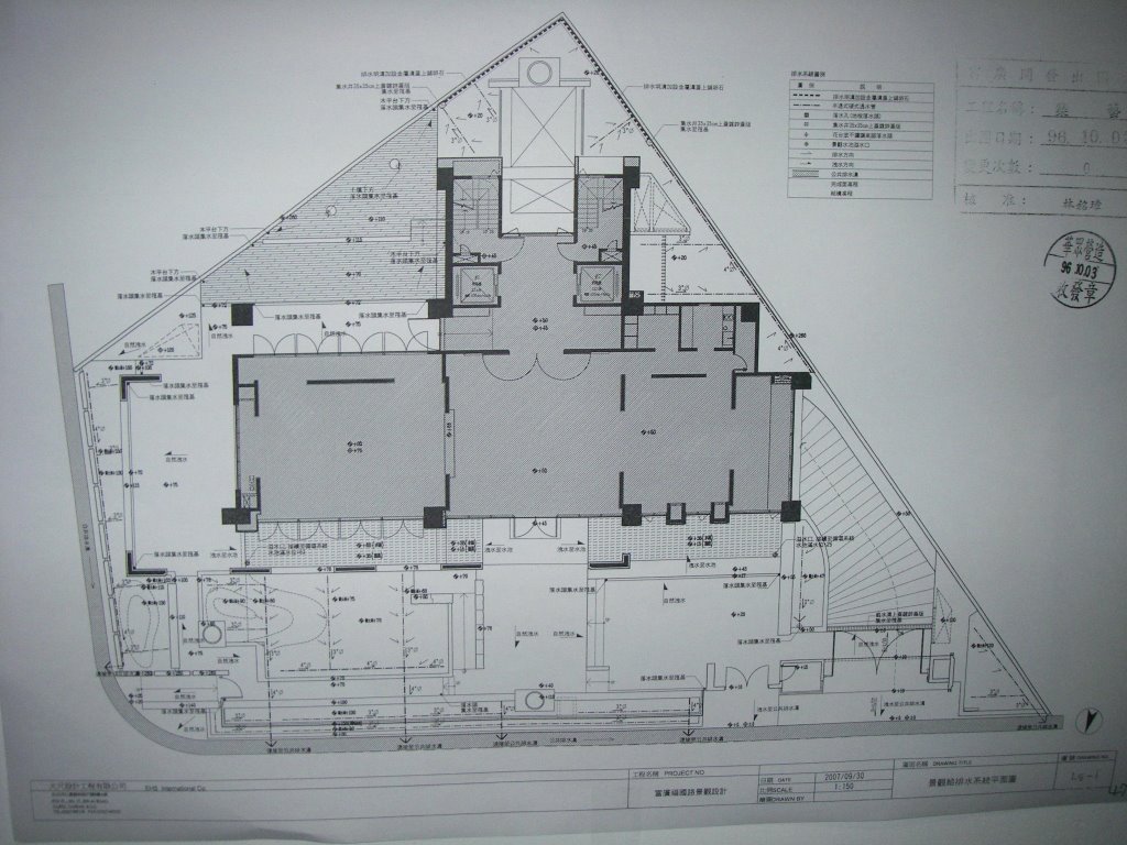
The Fu Guang Development Co., Ltd. -designed Zhuyi(築藝/2007-2009) building is located near a Taipei Station MRT stop exit, the Zhishan. Then, I was at work as an Senior Project Engineer.
Electrical circuits may be connected to ground (earth) for several reasons. In mains powered equipment, exposed metal parts are connected to ground to prevent contact with a dangerous voltage if electrical insulation fails. In electronic circuit theory, a "ground" is usually idealized as an infinite source or sink for charge, which can absorb an unlimited amount of current without changing its potential. Where a real ground connection has a significant resistance, the approximation of zero potential is no longer valid.
 Air admittance valves (also referred to as Durgo valves) are used to provided internal venting for soil and ventilating stacks - this can either be within rooms or the roof space. One great advantage of air admittance valves is that they remove the need for holes through the roof or external walls. They use also reduce the amount of pipework needed to fit an external, open soil or ventilating stack.
 The use of air admittance valves are governed by building regulations (Part H) and they cannot be used in all situation, these regulations should be checked before specifying the use of an air admittance valve - generally speaking, within a normal, two storey house with an existing vent pipe, there will be no problem; fitting within a taller building or a block of flats may be problematic.